Showing posts with label 46rh. Show all posts

Wednesday, April 21, 2010

Patience

When my wife gets antsy I tell her to put on her patience pants. She says she doesn't own any, and for that matter has never heard of such a thing. Personally, I feel my closet is full of them. But who am I to judge fashion. Anyway...


To all the dozens (well, maybe the 8 of you) that are interested in the final posts for the transmission rebuild, please be patient. I'm trying trying trying to get to it. My life is a bit more hectic then it was when I started this project. I'm trying to carve out some time to make these posts. I really want to! Between the 9-month-old, and now working 2 part-time jobs, plus the extra jobs I get on the side, there's just not a lot of minutes left. I'm sure each of you understand and can sympathize. But I promise I haven't forgotten.

Thanks again for reading!
Joel

Tuesday, December 01, 2009

Part 10 Rebuilding the Transmission Main Case: Rebuilding the Pump

This is a pretty easy step. Its straight forward and not too complicated.

The first thing to do is press in a new bushing into the pump body. I used a wood block to push it in flush with the pump body. Easy does it...of course. There is a special tool for this, for getting the depth just right, but I just centered the bushing between the inner and outer edges of the bore. It worked just fine.


Here's a sort of blurry photo of the bushing in place.


Now, in order to hold the bushing in place, you need to stake over an area that corresponds with one of the cutouts in the pump body. I just used a flat punch. It didn't take much to dimple the bushing out and into the pump body.


Now, the manual says to use a shop knife to cut off any burrs that may be in the area of where you staked the bushing. I thought, "Yeah, right, that won't work very well." Well, it worked wonderfully! The bushing material is quite soft. You do this twice 180 degrees apart from each other.


Here's a photo of the area I cut/smoothed with the knife.


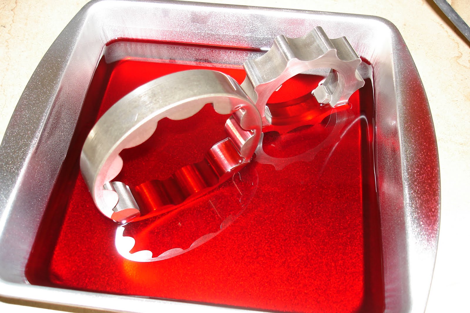
Now here's all the pieces we'll be working with. The pump body, the pump gears, the reaction shaft support over on the left side, two metal seals, and one plastic spacer/bushing.


I put a layer of fresh ATF all over the gears.


Slide the outer gear into the pump housing.


Then nest the inner gear inside of that. Make sure the drive dogs/teeth/whatever are oriented correctly. They face towards the front of the transmission.


I'm sorry that I don't have any photos measuring the pump gears for clearance. The first measurement is with a straight edge across the top of the gears/pump housing. The clearance should be .001" to .0025". The second measurement measure between an inner gear tooth and the outer gear, then between the outer gear and the pump body. These clearances should both be .0035" to .0075".

I did purchase a new gear set with all my parts I got for this rebuild. But when I got them installed and measured the clearances, they actually measured larger gaps (worse!) than the original pump. So I put the original pump gears back in.

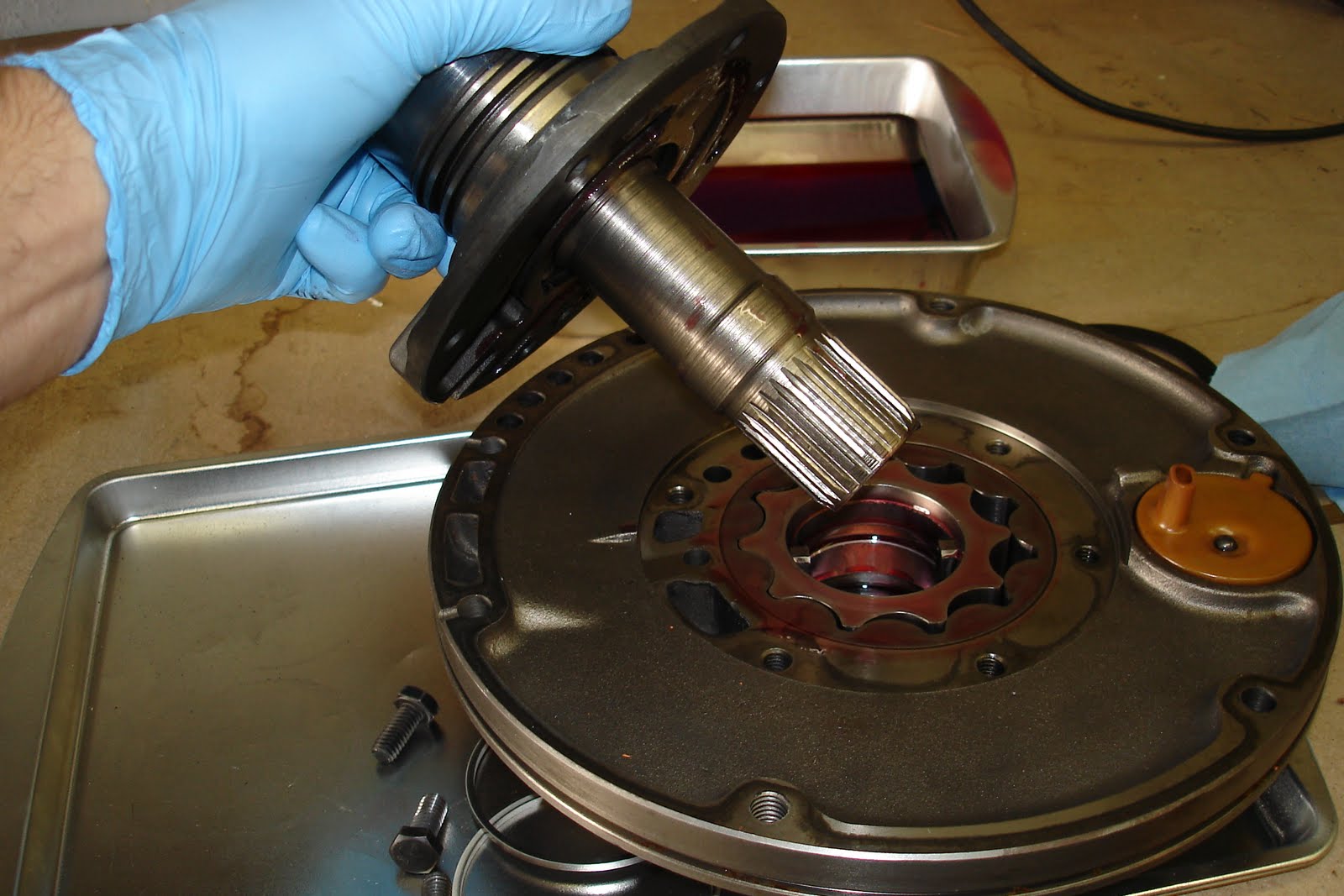
Now slide the reaction shaft support into the inner pump gear. There is a bushing inside the reaction shaft support. I didn't get a new one with my rebuild kit, and the old looked to be in pretty good shape. So I left it in place.


Thread in the six bolts. The reaction shaft support will only orient one way on the pump body since the bolt pattern is asymmetrical.


Torque those bolts to 175 in. lbs. That's 175 INCH pounds. So approximately 14.5 ft. lbs.


Slide the plastic thrust washer onto the reaction shaft support. I coated it with some assembly lube.


Now install the two metal style locking seal rings into the two grooves in the reaction shaft support. Of course, I used some assembly lube on those.


I made the locking tabs opposite each other. In other words, 180 degrees apart.


Next: Installing the O/D unit.

Tuesday, October 20, 2009

Part 9 Rebuilding the Transmission Main Case: Intalling the Front Band

Long time. I know. I now have a little daughter, aged 11 weeks. She's sleeping. And I finally have a little time to finish this write-up.

I opted for a heavier duty front band. It has Kevlar lining and it's also wider by a good bit...more holding power coupled with the higher ratio servo lever I installed along with a better servo.

Here they are side-by-side.


You can see that the original front band was definitely on its way out. You can see the cracking and flaking in this photo.


Soak the front band in some fresh ATF. It's big. So I had to work my way around letting it soak about 5 minutes in each position.


Here's a pic of the front band anchor and strut. The new strut is in the middle. The OEM strut is on the right. I opted for a thicker one. Just seemed stronger and a better idea. There's another step up from this. It was a billet strut. I didn't think I needed quite that much bling.


Now take the new front band and slide it over the front clutch retainer from the front side. The ears that interface with the strut and anchor go up (towards the pan and valve body). The front band slides in real easy.


Here's the front band in place looking down from the pan opening. Notice that this new wider band covers the entire surface of the clutch retainer and drum. Notice the band adjusting screw, on the right side in the case just next to the band, is adjusted all the way out.


Now place the new strut between the servo lever and the front band ear.


Place the front band anchor between the ear and the adjusting screw. Run the adjusting screw in to hold everything in place.


Here it is, all in place. Make sure to tighten the adjusting screw so that the band holds everything in place for now. You don't want those front and rear clutch assemblies to come out! Remember how hard those were to get in?


Next: Rebuilding the pump.

Monday, August 25, 2008

Part 8 Rebuilding the Transmission Main Case: Assembling the Front and Rear Clutch Assemblies and Installing Them in the Main Case

Ok. It's been 2 months moving on to 3 months since I posted here. I did this transmission build months ago! It's time to get this write-up finished!

First off. There's a fiber thrust washer that goes between the rear and forward clutches. The spec on this washer is .061-.063". I replaced mine since it came with the kit. The old one is the white one on the left. The new one was black.


Now install the rear seal ring on the input shaft. It's the larger seal here. The old one was a steel snap-end type. The new one was a teflon type with tapered ends. Also install the 2 front seal rings. They are also the teflon type. Assembly lube in the grooves and on the rings helps them to stay put.


Now install the fiber thrust washer in its groove on the rear clutch splined hub. A little fresh ATF here is good.


Take the front clutch assembly and smear some assembly lube on the bushing and sealing surface in its center.


Now take the front clutch assembly and slide it down over the input shaft. All those clutch pack teeth you just lined up will (hopefully) engage with the splines on the rear clutch hub. Work at it a bit. A little twist here and there helps. If you don't get it at first, maybe take the front clutch assembly back off and re-align the components then try again. Or maybe you'll get lucky and it will just slide right on! That didn't happen for me!


When you get the front clutch nested down nicely on the rear clutch it should look something like this.


Turn the clutch assembly over and set it somewhere so that it can rest on its own. I used the opened jaws of my vise.


Now, in the end of the input shaft, the eye that's looking up at you from the center of the rear clutch, is where the intermediate shaft thrust washer goes.


My rebuild kit came with several thicknesses. I chose the thickness that most closely matched the one I took out. You can see my original on the bottom left with the wear marks.


Apply some assembly lube to the washer so that it stays in it's spot when you install the clutch assembly into the main case.


The thrust washer fits into the end of the input shaft only one way because of the arrangement of the three ears. Make sure the groove is facing up, or to the rear of the transmission.


Now center and align the teeth of the friction components of the rear clutch. They nest down over the outside of the front annulus gear that's inside the driving shell already installed into the main case.


Here are two photos of the rear clutch installed into the driving shell WITHOUT front clutch. This is just to sort of give you an idea of how it fits in.


Now install the clutch assembly with the input shaft into the main case. Now that I'm done with this project, I can, without a doubt, say that this was the ABSOLUTE MOST frustrating part of this whole job. Grrr! The Factory Service Manual said to place the case in an upright position. I tried that. It worked about as well as standing on my head. Trying to do it with the case horizontally worked about as well as trying to breath underwater! All the friction pieces tend to get misaligned, and then you have to pull the pieces apart, re-align it all, then try again. All the while getting more and more ATF all about your person. So, patience, I guess. Just make sure, in the end, that the thrust washer that you just installed on the end of the input shaft stays. It tended to "migrate" to other parts of the transmission with little bumps.

Now, I hesitate to mention this part, but once you get this all assembled, you're likely to have to pull it apart again! After you install the pump and housing in the front of the case, you have to take a measurement for input shaft end play. If it's wrong (and mine was) you'll need to replace the thrust washer with a different thickness. Glory be! I'll detail that procedure a little later.

Here's a pic of the clutch assembly finally installed into the main case. You can see here how the teeth on the front clutch retainer mesh into the slots on the driving shell of the intermediate shaft/planetary assembly...but not quite! So I don't have the last friction engaged with the splines correctly! Grrrr!


And here's a more general photo of all the pieces in the main case. I have the case in the "vertical position" the FSM so gloriously refers to her. Here the front clutch retainer and driving shell are interfacing much more appropriately.


Next: Installing the front band.


Wednesday, June 11, 2008

Part 7 Rebuilding the Transmission Main Case: Rebuilding the Front Clutch

I'll set the rear clutch aside, and start working on the front clutch. The front clutch engages when the main case is in direct (which translates to 3rd and 4th gears) and in reverse. This is what was toasted in my transmission prompting this rebuild. My symptoms were that the transmission wouldn't shift into 3rd and was slow to engage reverse. The problem was the seal on the clutch piston. It had a chunk out of it. And the clutch steels and frictions were literally toasted. This, I believe, is a failure due to upgrades. Last year I upgraded the torque converter to a Hughes XFM15 low stall unit. It gets more power to the ground. I also installed a TransGo shiftkit. These two items, coupled with the fact that a few years back my throttle valve (TV) cable fell off while towing trailer, helped this "burning issue" happen. When the TV cable came off , the ATF temperatures rose almost instantly to 350 degrees. The front clutch was "engaging" but with no holding force from line pressure which the TV cable controls.

Here's the original clutch pack in all its toasty-glory! Most of the friction material is gone from all the friction elements. And the pieces have taken on a conical warp-ed-ness! It had 4 frictions and 4 steels.


You can refer to my post on tearing down for more carnage pics.

Here's the new clutch pack. I upgraded to a pack with 6 frictions and 6 steels. That gives me 50% more clutch apply area than OEM. Hopefully this horrible mess won't happen again!


Place the frictions and steels in some fresh ATF and let them soak (at least 30 minutes) while you ready the clutch retainer/drum.


Start by drifting out the front clutch retainer bushing. Mark or take note how far the bushing is pressed into the bore of the retainer so that you can install the new bushing to the same depth. The "special tool" figures this out for you. I didn't have that tool, so I made a mark. Be ultra careful to not score the sealing surfaces just above the bushing. The bushing came out pretty easily.


Then press the new bushing into the clutch retainer. Yes, that's the old pump gear I'm using to press with. It was just the perfect size. Once the bushing is flush I used the old bushing stacked on top of the new bushing in order to press it a little further into the retainer.


Here's the bushing in its final resting place.


Now install a new outer seal into its associated groove in the clutch piston. Make sure the lip faces down, or to the front of the transmission.


Now install the inner seal into its groove on the clutch retainer hub. Again, make sure the lip faces down, or towards the front of the transmission. The bottom groove , or the groove nearest to the base of the retainer, is the seal groove. The top groove is for spring retainer snap ring.


Lube all that mess up with some assembly lube. Note: this is NOT the direction the piston is installed!


Flip the piston over and slide it down into the clutch retainer. Go easy, and make sure the lips on the seals don't get folded over. You may need to use a tool to work the lips into the bores. There's a special tool for this which I don't have. I used a .010" feeler gauge. Again, go easy and take your time.


Place the 9 piston springs over the little "spring nubs" (technical term). If you have a different transmission application you may have 11 or 13 springs which would be installed in a different pattern.


Now install the spring retainer over the springs. Mine was a bit "deformed." But I mushed it back into shape with a hammer and decided to reuse it.


There's also a special tool for compressing the springs and retainer. I used these two clamps. It worked. Although not ideally. If I were to do it again, I would figure out a better solution than this. "Gee, I wonder why the spring retainer was deformed?" Could be because of this technique!


Here's the spring retainer compressed and ready for the snap ring.


The snap ring installed and the clamps removed.


Now I'm ready to install the clutch pieces. Start with a steel. It goes right on top of the piston.


Here's the first steel in place.


Now take a friction from the ATF.


And install it on top of the steel in the clutch retainer. Alternate steel-friction-steel-friction until you've installed them all.


The upgraded clutch pack came with a thinner reaction plate to accommodate the thicker pack. The new one measured right around .132".


The old one measured .280".


Place the new reaction plate on top of the last friction.


Here's the clutch pieces all in place with the reaction plate on top.


Install the wave style snap ring in its associated groove.


The clutch pack all assembled with the snap ring in place.


Now measure the clutch pack clearance. Insert the feeler gauge(s) between the top of the reaction place and the bottom of an "upward wave" in the snap ring. In other words, where you would naturally find a gap. Mine measured in at .070" which is right about where I wanted it for this upgraded clutch pack (according to some transmission gurus I chatted with). This gives me .010" clearance per clutch element for lube to enter when the clutch is not engaged. If you're installing an OEM setup with 4 frictions and 4 steels, the manual states .082" to .151".


Next: assembling the front and rear clutch assemblies and installing them in the main case.