The first thing to do is press in a new bushing into the pump body. I used a wood block to push it in flush with the pump body. Easy does it...of course. There is a special tool for this, for getting the depth just right, but I just centered the bushing between the inner and outer edges of the bore. It worked just fine.

Here's a sort of blurry photo of the bushing in place.

Now, in order to hold the bushing in place, you need to stake over an area that corresponds with one of the cutouts in the pump body. I just used a flat punch. It didn't take much to dimple the bushing out and into the pump body.

Now, the manual says to use a shop knife to cut off any burrs that may be in the area of where you staked the bushing. I thought, "Yeah, right, that won't work very well." Well, it worked wonderfully! The bushing material is quite soft. You do this twice 180 degrees apart from each other.

Here's a photo of the area I cut/smoothed with the knife.

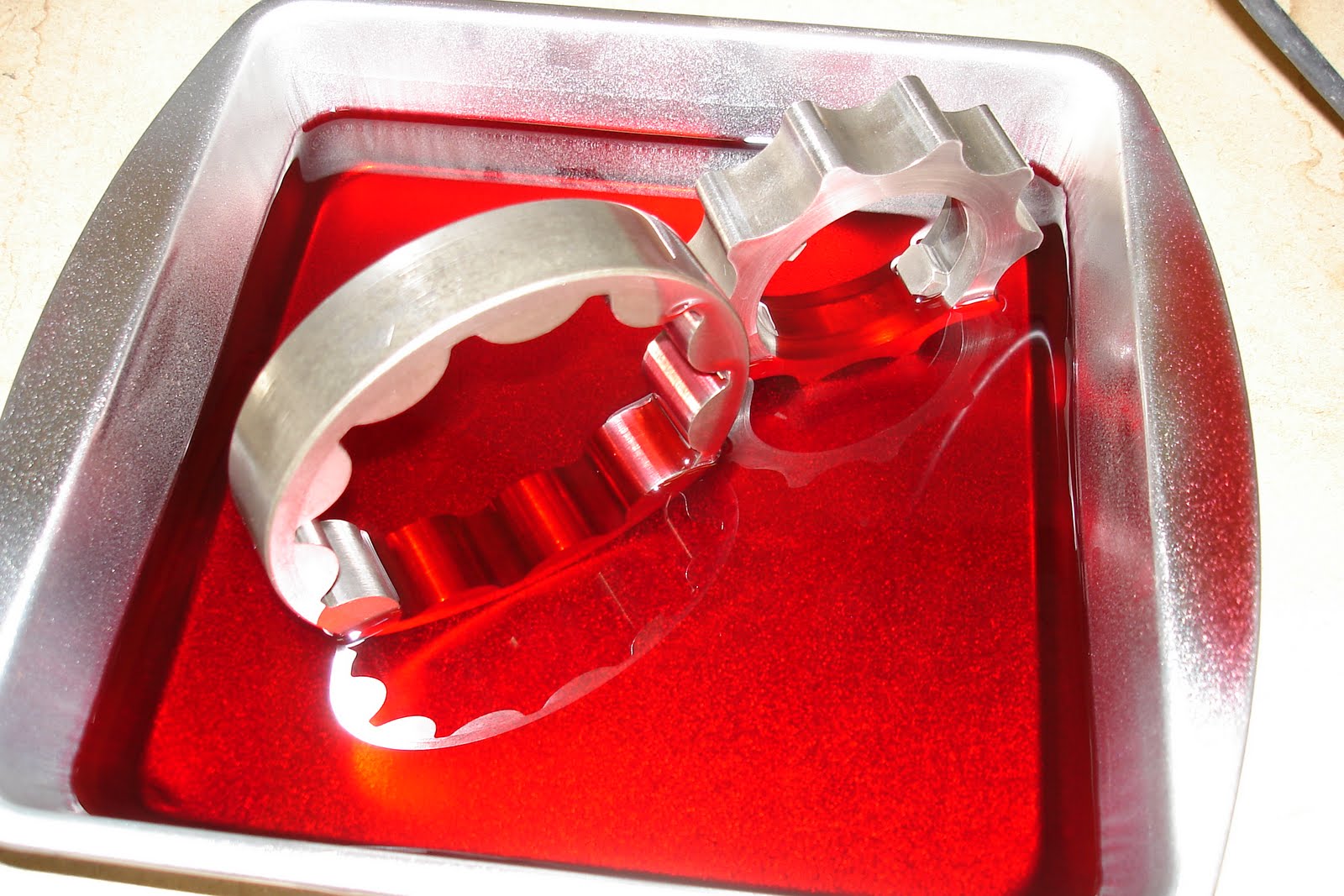
Now here's all the pieces we'll be working with. The pump body, the pump gears, the reaction shaft support over on the left side, two metal seals, and one plastic spacer/bushing.

I put a layer of fresh ATF all over the gears.
Slide the outer gear into the pump housing.

Then nest the inner gear inside of that. Make sure the drive dogs/teeth/whatever are oriented correctly. They face towards the front of the transmission.

I'm sorry that I don't have any photos measuring the pump gears for clearance. The first measurement is with a straight edge across the top of the gears/pump housing. The clearance should be .001" to .0025". The second measurement measure between an inner gear tooth and the outer gear, then between the outer gear and the pump body. These clearances should both be .0035" to .0075".
I did purchase a new gear set with all my parts I got for this rebuild. But when I got them installed and measured the clearances, they actually measured larger gaps (worse!) than the original pump. So I put the original pump gears back in.
Now slide the reaction shaft support into the inner pump gear. There is a bushing inside the reaction shaft support. I didn't get a new one with my rebuild kit, and the old looked to be in pretty good shape. So I left it in place.
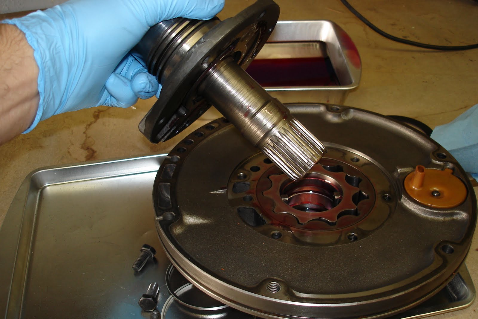
Thread in the six bolts. The reaction shaft support will only orient one way on the pump body since the bolt pattern is asymmetrical.

Torque those bolts to 175 in. lbs. That's 175 INCH pounds. So approximately 14.5 ft. lbs.

Slide the plastic thrust washer onto the reaction shaft support. I coated it with some assembly lube.

Now install the two metal style locking seal rings into the two grooves in the reaction shaft support. Of course, I used some assembly lube on those.

I made the locking tabs opposite each other. In other words, 180 degrees apart.

Next: Installing the O/D unit.


.JPG)