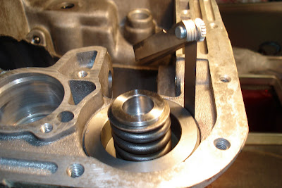
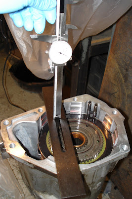
I met with some difficulty with this step. It all turned out fine in the end, but, MAN, was I ever pullin' my hair out!
As always, soak the friction components in some fresh ATF. At least 30 minutes is recommended.

First off, I decided to upgrade this clutch pack. Everyone seems a little shy about pulling loads in O/D. So I figured it would be a good idea to have as much ooomph here as possible.
The original clutch pack had 5 steel pieces, 5 friction pieces, and 1 reaction plate. The frictions were really in pretty good shape. The steels show a little wear.

The new clutch "power pack" has 6 steels, 6 frictions, 1 thinner reaction plate, and 1 thinner snap ring. This will give me a 20% increase in surface area over the OEM setup.

The old reaction plate measured right around .215" thick (give or take).

The new reaction plate is .185" thick.

The old snap ring was about .078" thick (again, give or take).

The new snap ring is .060" thick.

Now this is where my headaches started. I started stacking up the components of the clutch and it was obvious, rather quickly, that it was just too thick! Here, the groove the retaining ring is supposed to fit in is covered by the last steel. There's no way to get it in. Even if I could force it in the pack would be waaay too tight and burn up in a hurry.

Head scratching. Lots of head scratching. Maybe some cursing.
So after some consulting with the boys over at the
Diesel Truck Resource forum (which has invaluable advice on most subjects), and a call to
PATC (where I purchased the parts), I discovered that I was NOT supposed to put in the wave snap ring at the bottom of the stack as the OEM configuration had. THAT would have been nice to know from the beginning. Maybe somebody (
PATC) should include some instructions on what to do with their upgrade power packs.
I did some more reading over at the
Diesel Truck Resource forum. Most noteably, there's a thread that user BC847 wrote up about his
transmission rebuild. I'm doing most of the upgrades he did, and he said he had .050" milled off his reaction plate for teh overdrive clutch. I thought about this for minute and headed out to the garage with my micrometer.
This is what I found. The new clutch pack DID fit without the wave snap ring. But there was only about .010" clearance between the top steel and the retainer ring. That didn't seem like enough to me for lube clearance when the clutch is disengaged. So, voila, add .050" to this figure and you get .060" clearance, or about .010" clearance per clutch.
I had a local machine shop take .050" off the bottom of the reaction plate. Just enough for the snap ring to fit in.
(BTW, I used an simply CAD application from
eMachineShop.com to draw up a model of what I wanted done. It worked fairly well...enough for the machinist to know what I was talking about. It generates a nice 3D image as well. Give it try.)

OK. NOW I'm ready to assembly the dern thing!
Place the new flat snap ring in the groove at the bottom.

Make sure it's fully seated in its groove.

Now, normally you would install the wave ring on top of the snap ring. But in my installation I'm NOT doing that because of the upgraded clutch pack.

Flip the reaction plate over, so the machined shoulder fits next to the snap ring, and place it on top of the ring.


Now, start installing the frictions and steel. Start with a friction.


Now install a steel over the friction.


Alternate friction, steel, friction, steel until you have all 12 componants installed. (This photo has the wave ring at the bottom. I didn't install it in the final assembly.)

Install the associated retaining ring in its groove. It's a wire type.


Here's the .060" clearance between the top steel and the retaining ring.

And the whole clutch pack in its final assemblage.

Next: taking the final measurements for the intermediate shaft shim and the overdrive piston thrust plate.


